Supports and Springs
- Choose custom in the node Support inspector for independent global horizontal (DX), vertical (DY), and rotational (RZ) restraint checkboxes. Checked means restrained. Existing free/pin/roller/fixed presets remain available. Custom support symbols show horizontal/vertical restraint lines and a square for rotational restraint; hovering identifies the restrained degrees of freedom.
- Node properties include Spring DX, DY, and RZ stiffness. Zero means absent; positive values create bilateral springs along global X/Y or about global Z. Translational stiffness uses force/length; rotational stiffness uses moment/rad in the selected unit system. A rigid restraint and a spring cannot occupy the same direction: explicitly free that direction or set its spring to zero. Springs and releases are also editable atomically through bulk properties and Model Tables, with normal undo/redo and result invalidation.
Inclined rollers (development after RC4): in a 2D node's Properties, choose
Support inclined and enter Roller tangent (deg), then Apply. The angle is
counterclockwise from global +X, between -180° and +180°. The roller fixes
translation along normal = (-sin alpha, cos alpha) and leaves its tangent and
RZ free: 0°/180° restrain DY; 90° restrains DX. The canvas symbol, tree, tooltip
and printed definition show the inclination. Model Tables and bulk properties
provide the same staged edits, with one undo and normal result invalidation.
Use File > Examples > 2D Frames > Beam - Inclined Roller for a ready-to-solve 120 in beam with a pin and a 30° roller under -0.01 kip/in. Service reactions are N1 FX +0.346410 / FY +0.6 kip, N2 FX -0.346410 / FY +0.6 kip; the rigid normal reaction is +0.692820 kip. Reverse flips the reactions.
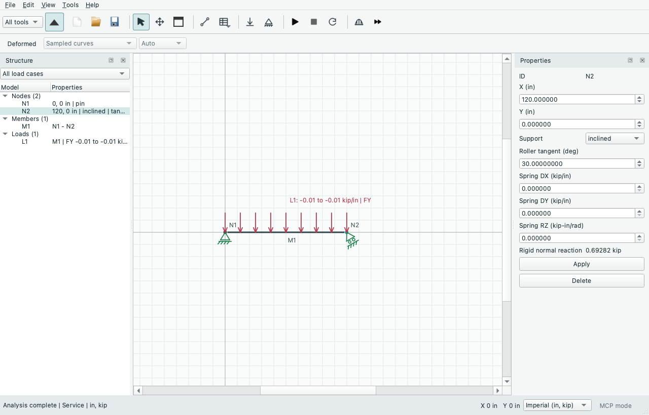
Reactions in ordinary tables remain global totals. Existing bilateral springs
keep their global axes; rigid and spring reactions are computed separately and
summed. A spring cannot occupy a global direction fixed exactly by the roller's
normal. Other global springs can act along the permitted motion. Properties shows
the signed rigid normal force; MCP node reads include paginated inclined_supports
metadata, separate global FX/FY/MZ (2D) or FX/FY/FZ/MX/MY/MZ (3D) rigid/spring
vectors, normal force and explicit display units. A total reaction with springs need not point along the roller normal.
3D normals: choose Support inclined, then set Normal azimuth (deg)
from global +X toward +Z (-180° to +180°) and Normal elevation (deg) toward
+Y (-90° to +90°). Unlike the 2D tangent angle, these specify the normal:
normal = (cos(el)*cos(az), sin(el), cos(el)*sin(az)). Translation along that
normal is fixed; two tangent translations and all rotations are free. Azimuth 0°
and elevation 90° give the ordinary global-Y roller. The viewport pad faces the
normal, its two rollers identify permitted sliding, and hover lists the normal
beside the six global directions. Orthographic reports project the same direction
and print its global XYZ components even when it points out of the view.
Optional global restraint checkboxes add constraints to a 3D inclined support. They are also available in Model Tables and bulk edits. Changing a preset to inclined starts with no additional restraints; select those you need explicitly. An exactly redundant normal does not create an extra reaction: its separate normal force is reported as zero and the additional global restraints own that reaction. Nearly dependent constraints are rejected. Rigid/spring vectors include all additional global support forces and couples.
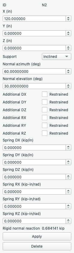
Try File > Examples > 3D Frames > 3D Cantilever - Oblique Roller Normal:
azimuth 60°, elevation 30°, normal (0.433013, 0.5, 0.75). It includes normal,
reversed and zero load combinations and a Properties readout of the solved normal
force. This native offscreen capture shows the staged controls; the separate
viewport checks verify its rendered orientation and pick identity.
Inclined supports work with linear frames, axial trusses and supported end releases in both dimensions, including shared nodes in the existing experimental coupled-shell workflow. All existing surface/release compatibility and shell force/moment rejection gates still apply. Create 3D Copy preserves the physical normal; Preserve planar constraints additionally fixes DZ/RX/RY. Its source is unchanged. Previewed transforms retain support directions in global axes; support copying is explicit and conflicts at reused joints remain rejected.
P-Delta supports inclined rollers within the existing frame-only scope. Each combination starts with an elastic preload, updates PyNite's geometric stiffness, and repeats until free physical forces/moments close (at most 30 updates). This extra convergence step matters when an oblique reaction changes axial strain; it also closes the engine's axial geometric-stiffness contribution, so results can differ slightly from its ordinary two-step solve. Effective constrained stiffness must remain positive definite. Failure or nonconvergence rejects the snapshot. As for other P-Delta results, global equilibrium checks forces only; undeformed moment arms do not include second-order effects. P-Delta with trusses, released translations, spatial rotational releases or surfaces remains unsupported. Imposed support movements are available in linear analysis and supported frame-only P-Delta as described below; unilateral contact and plastic connections remain separate tasks.
Production uses sparse node-local free coordinates and unchanged engine member stiffness/fixed-end vectors. Global physical displacements drive ordinary member recovery. Constrained rigid-body checks, dense/sparse stiffness checks, a pre-cancellation projection roundoff bound, free physical equations and independent global equilibrium for every combination must pass. No penalty stiffness or unused- rotation gauge grounds a physical mechanism. Independent cantilever flexibility, pin/roller nodal/member fields, six-DOF spatial compliance, signed/zero combinations, global springs, released-end recovery, trusses, conversion, shared surface nodes, independent dense P-Delta compliance/axial references, sparse stability and actual worker transport are regression-tested. The earlier test-only dense feasibility report remains reproducible separately (153 reference cases and six rejected configurations); it does not publish application snapshots:
uv run python -B scripts/benchmark_inclined_supports.py --output /tmp/inclined-support-feasibility.json
The prototype's quadratic-energy identity concerns equivalent nodal equations; it does not validate total distributed-load strain-energy recovery. Nonlinear connections remain separate work; production second-order support movements are covered below.
Imposed support settlements and rotations (development after RC4): select a supported node and enter Imposed DX/DY/RZ in 2D, or DX/DY/DZ/RX/RY/RZ in 3D. Only directions with explicit rigid global restraints are offered. Translation uses the current length unit; rotations use radians, with the right-hand sign rule. Apply commits the complete edit with one undo. Model Tables and bulk properties offer the same quantities. Removing a restraint through the native controls clears its inapplicable motion; MCP edits must clear incompatible values explicitly in the same batch.
For an inclined roller, Imposed normal is signed along its displayed global
normal: normal dot displacement = settlement_normal. It does not prescribe
motion along the tangent. A 3D inclined support can also have global prescribed
movements on its additional rigid restraints. Redundant constraints must prescribe
the same motion; incompatible global/normal or shared-edge prescriptions reject
the model/analysis. Exact redundant normals still have zero separate normal
reaction, with the global restraints owning that reaction.
These are model-level prescriptions, applied unchanged in every load
combination, including a combination with all load factors zero. A reverse load
combination reverses the loads; it does not reverse the settlement. Linear load
increments superpose about the same prescribed-motion state; adding complete
combination responses would count the settlement twice. Bilateral springs retain
zero rest displacement: their reactions remain -k * global displacement, not
-k * displacement relative to the imposed motion. Spring rest-position movement,
case-specific prescriptions and staged construction are not provided.
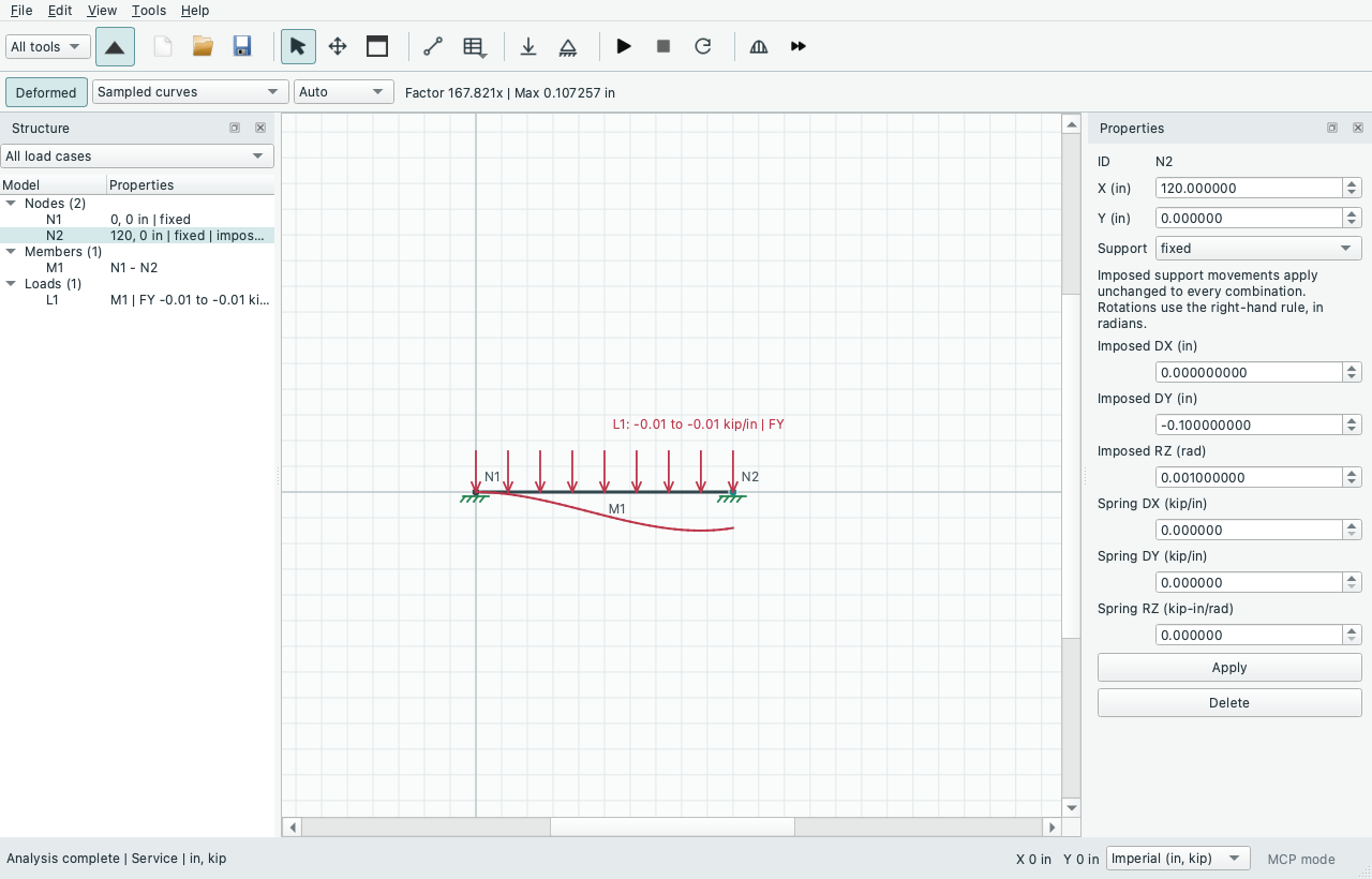
Try File > Examples > 2D Frames > Beam - Support Settlement and Rotation. The 120 in fixed-ended beam carries -0.01 kip/in; its right support moves DY -0.1 in and RZ +0.001 rad. Settlement only sets the applied-load factor to zero but retains those support motions. Its reactions are:
| Node | FY (kip) | MZ (kip-in) |
|---|---|---|
| N1 | +16.433333 | +862.75 |
| N2 | -16.433333 | +1109.25 |
Service adds +0.6 kip at each end, +12 kip-in at N1 and -12 kip-in at N2 from the distributed load. Reverse load reverses only those load contributions. The native offscreen capture shows prescribed inputs and scaled solved deformation.
Scope: linear frames, trusses and supported releases in 2D/3D, plus prescribed frame joints in the existing experimental coupled-surface workflow. Generated mesh-edge support motions remain zero unless the joint has an explicit compatible frame-node prescription. Existing surface/release, drilling and independent force/moment gates remain active. P-Delta also supports rigid-support motions within its existing frame-only scope: no trusses, surfaces, released translations or spatial rotational releases. Planar moment releases retain zero member-end moments; a prescribed disconnected joint rotation does not rotate that member end.
The constrained solver adds a particular physical motion to the free-coordinate solution and subtracts its stiffness contribution from the free load vector. It checks physical joint equations and independent global equilibrium for every combination, including the zero-load state. Independent beam stiffness/Hermite fields, six-DOF compliance, zero-force rigid-body motion, ground-spring laws, released-end recovery, trusses and shared-node checks cover this workflow.
For P-Delta, each geometric-stiffness update acts on both the free response and the prescribed motion. Support shortening can therefore create axial preload and second-order response even with no applied loads. Each complete combination is solved independently; neither load-response nor settlement-response superposition is valid in general. Springs retain their global zero rest positions. Physical free equations must converge and the effective stiffness must remain positive on every free mode; otherwise no snapshot is accepted. The usual P-Delta force-only global equilibrium convention remains, since undeformed moment arms omit second-order effects.
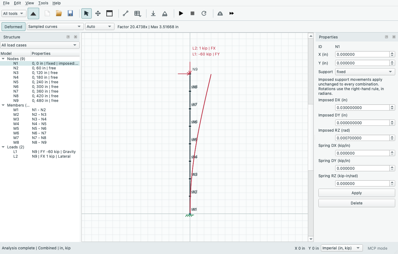
Try File > Examples > P-Delta > Column - Imposed Base Motion. The native example shows the prescribed base inputs and amplified sampled deformation; read numerical nodal values in Results. Combined tip DX is about 3.51866 in, Gravity about -0.473713 in, and Base motion only is -0.306 in.
Independent checks compare refined fields with the exact elastic beam-column
equation EI*w'''' + P*w'' = q, including compression/tension, base translation/
rotation, imposed shortening, uniform loads and ground springs. A separate spatial
reference integrates Hermite strain energy and enforces affine constraints with
Lagrange multipliers, closing axial compatibility through a scalar root. The
engine's geometric matrix includes an axial N/L term: for force-controlled
uniform axial response the strain-derived tension-positive preload satisfies
N + N^2/(EA) = applied axial force. This is the engine's small-strain geometric-
stiffness convention, not a finite-strain material law. Mesh refinement remains
necessary; interior P-Delta member recovery remains approximate. Buckling,
nonconvergence and unsupported entities still reject the analysis.
Support tooltips, the model tree, 3D hover and printed definitions identify the
imposed motions and their units. MCP node-result pages include
imposed_support_movements with explicit display units and the model-level note;
normal and unused-rotation metadata remain available alongside it. read_schema
provides the exact settlement_* fields and a valid batch example. Inputs are
canonical inches/radians. Movements copy only when Copy supports is chosen;
collision checks include their values, and global orientations stay global.
Changing a prescription invalidates results; changing display units retains the
snapshot and converts its labels.
Source: GUIDE.md. This manual follows the current repository; the published rc1 wheel has a smaller feature set.